
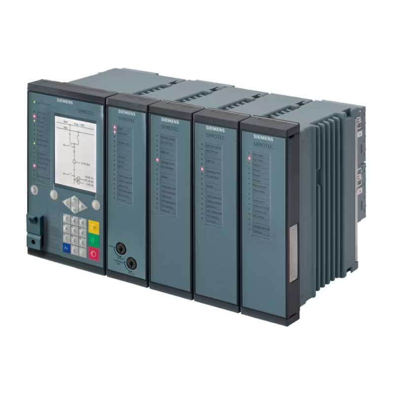
Siemens SIPROTEC 7VU85 High-Speed Busbar Transfer Device
Siemens SIPROTEC 7VU85 High-Speed Busbar Transfer Device Suppliers,Exporters in India
ARP IMPEX is a supplier and exporter of Siemens SIPROTEC 7VU85 High-Speed Busbar Transfer Devices in India. We handle requirements for power plants, petrochemical units, refineries, steel plants, pharmaceutical facilities, data centres, hospitals and other installations where an interruption in motor-bus power can stop the complete process.
The Siemens SIPROTEC 7VU85 is used to transfer a busbar from its normal incoming power source to an alternative source when the running incomer fails or becomes unsuitable.
It continuously monitors the normal incomer, standby incomer and busbar voltage. When it detects a valid transfer condition, the device opens the faulty or unavailable source and closes the alternative source through a controlled transfer sequence.
This is particularly important on medium-voltage busbars supplying large induction motors. After the main source is disconnected, the motors continue rotating and generate a decaying residual voltage on the busbar. Closing the standby source without checking this voltage can create heavy current, torque shock and stress on motors, couplings, cables and switchgear.
The 7VU85 checks the electrical conditions and selects the permitted transfer method before issuing the closing command. Depending on the situation, it can perform a very fast transfer, in-phase transfer, residual-voltage transfer, long-time transfer or parallel transfer.
The device is built on the modular Siemens SIPROTEC 5 platform and can handle simple two-incomer schemes as well as larger systems with sectionalised busbars, double busbars and several incoming sources.
For Siemens SIPROTEC 7VU85 price and availability, send the complete Siemens order code, required busbar scheme, quantity and destination country.
What the Siemens 7VU85 Does
Industrial motor busbars are often supplied through two independent sources:
- One normal running incomer
- One standby or alternative incomer
During normal operation, the primary source supplies the busbar while the alternative source remains available.
The transfer may be required because of:
- Failure of the normal incoming source
- Protection operation on the incomer
- Incoming circuit breaker opening unexpectedly
- Undervoltage at the normal source
- Underfrequency condition
- Transformer failure
- Generator trip
- Utility supply disturbance
- Manual source-change request
- Planned maintenance of the running incomer
- A plant control-system command
- Another user-defined start condition
After receiving the transfer start, the 7VU85 checks the status of both sources, the busbar condition and the relevant circuit breakers.
It then carries out the configured switching sequence. The aim is to restore power quickly without closing the alternative source at an unsafe voltage or phase-angle condition.
High-Speed Transfer for Motor Busbars
Large motors do not stop immediately when their electrical supply is removed.
They continue rotating because of their mechanical inertia and begin feeding a residual voltage back into the busbar. The magnitude and frequency of this voltage decrease as the motors slow down.
If the standby source is closed when its voltage is badly out of phase with the residual busbar voltage, the motors may experience:
- High transient current
- Severe electromagnetic torque
- Shaft and coupling stress
- Motor winding stress
- Circuit-breaker stress
- Process-equipment disturbance
- Protection relay operation
- Failure of the transfer sequence
The Siemens 7VU85 measures the source and busbar conditions before closing the standby incomer.
Where the electrical conditions permit, the device can complete the transfer within a very short interruption time. A short transfer helps the connected motors remain close to their normal speed, reducing the possibility of process shutdown or difficult motor restarting.
Siemens 7VU85 Transfer Modes
The actual transfer method depends on the selected scheme, system condition and configured settings.
Fast Transfer Mode
Fast transfer is used when the alternative source and the busbar voltage remain within the permitted voltage, frequency and phase-angle conditions.
The device opens the running incomer and closes the standby incomer with minimum delay.
This mode is useful where the source disturbance is detected early, and the motor-bus residual voltage has not moved far away from the alternative source.
Real-Time Fast Transfer Mode
Real-time fast transfer uses continuous electrical measurements and an improved switching algorithm to determine whether the alternative source can be connected quickly.
Siemens states that the 7VU85 can provide transfer times of up to approximately 10 milliseconds in suitable applications. The actual plant transfer time also depends on circuit-breaker operating times, wiring, logic and the selected transfer sequence.
This mode is useful for critical motor loads where even a short voltage interruption can affect production.
In-Phase Transfer Mode
If fast transfer is not possible, the device can wait for the rotating motor-bus voltage to move into an acceptable phase relationship with the alternative source.
It predicts the movement of the residual voltage and issues the closing command so that the circuit breaker closes when the phase difference is within the selected range.
This can allow the motors to remain connected without waiting for the busbar voltage to fall to a very low level.
Residual-Voltage Transfer Mode
Residual-voltage transfer is used after the motor-bus voltage has decayed below a set value.
At this lower voltage, the risk of a severe out-of-phase closing condition is reduced. The device then permits the standby incomer to close.
This method normally takes longer than fast or in-phase transfer but may be required when the source and busbar conditions do not allow an earlier connection.
Long-Time Transfer Mode
Long-time transfer is used when the busbar must remain disconnected for a set period or until additional closing conditions are satisfied.
It may be applied when:
- The source condition is uncertain
- Motors must slow down before reconnection
- Process requirements permit a longer interruption
- External interlocks must clear
- A controlled restart sequence is required
- Fast transfer conditions are not met
The connected motors may need to restart after a long-time transfer, depending on how far their speed has fallen.
Parallel Transfer Mode
Parallel transfer allows the alternative incomer to close before the running incomer opens.
For a brief period, both sources operate in parallel. The source is then disconnected.
This transfer method avoids an interruption in busbar voltage, but it can only be used where paralleling the two sources is permitted.
The 7VU85 can use synchrocheck and synchronising conditions before allowing parallel transfer. The system fault level, transformer arrangement, source phase relationship and utility regulations must also allow temporary parallel operation.
Transfer Sequences
The Siemens 7VU85 supports different circuit-breaker operating sequences.
Sequential Transfer
In a sequential transfer, the running incomer opens first. After the open status is confirmed and the closing conditions are satisfied, the alternative incomer closes.
This is a common arrangement where the two incoming sources must not operate in parallel.
Simultaneous Transfer
In a simultaneous sequence, opening and closing commands may be issued with closely coordinated timing.
This can reduce the dead-bus period, but the circuit-breaker operating times must be known and entered correctly.
Parallel Transfer
The alternative source closes first after synchronising conditions are met. The source then opens.
This arrangement provides a closed transition without a break in supply, where the plant network permits source paralleling.
Busbar Arrangements Covered
The Siemens SIPROTEC 7VU85 can be configured for several primary switching arrangements.
Typical schemes include:
- Single busbar with two incomers
- Sectionalised single busbar with two incomers
- Single busbar with three incomers
- Double busbar with two incomers
- Sectionalised double busbar with three incomers
- Busbar with utility and generator supplies
- Busbar with multiple transformers
- Motor busbar with normal and standby sources
- Bus coupler and bus-section transfer schemes
- Complex schemes with several standby-source priorities
Siemens provides predefined application templates for common industrial and power-plant arrangements.
For larger systems, the modular hardware and programmable logic can be configured for applications involving up to 20 circuit breakers.
Technical Specifications
The Siemens SIPROTEC 7VU85 is configured according to the actual busbar and switching arrangement. The hardware and functions depend on the complete order code.
- Brand: Siemens
- Product family: SIPROTEC 5
- Model: 7VU85
- Product type: High-speed busbar transfer device
- Main application: Automatic transfer between normal and alternative power sources
- Primary use: Medium-voltage motor busbars and critical industrial supplies
- Busbar arrangements: Single, sectionalised single and double busbar schemes
- Incoming sources: Two or more sources, depending on configuration
- Circuit breakers: Complex applications with up to 20 circuit breakers
- Transfer initiation: Automatic, manual, local, remote or user-defined
- Transfer sequences: Sequential, simultaneous and parallel
- Transfer modes: Fast, real-time fast, in-phase, residual-voltage and long-time
- Fast transfer time: Up to approximately 10 ms under suitable conditions
- High-speed outputs: Approximately 1 ms operating time on applicable output contacts
- Synchrocheck: Available for parallel transfer
- Current inputs: Depend on selected hardware
- Voltage inputs: Depend on busbar and incoming-source arrangement
- Binary inputs and outputs: Modular and expandable
- Predefined hardware variants: Available for common transfer schemes
- Maximum hardware expansion: Depends on the selected SIPROTEC 5 housing and modules
- Engineering software: Siemens DIGSI 5
- Display: Graphic display with single-line representation on applicable versions
- Local operation: Device panel and web-based interface
- Mounting: Flush or surface mounting, depending on housing
- Communication: Serial and Ethernet options
- IEC 61850: Reporting, GOOSE and process-bus options
- Additional protocols: IEC 60870-5-103, IEC 60870-5-104, Modbus TCP, DNP3 and PROFINET options
- Merging-unit function: Available with the required configuration
- Recording: Event, fault and transfer-direction recording
- Cybersecurity: SIPROTEC 5 security functions, depending on configuration
- Auxiliary supply: Selected according to the complete device order code
- Protection functions: Standard protection functions can be added
- Control functions: Circuit-breaker control, interlocking and programmable logic
These are general family-level details. The current inputs, voltage inputs, binary I/O, housing, power supply, communication modules and functional scope must be checked from the complete Siemens 7VU85 order code.
Transfer Start Conditions
The high-speed transfer can be initiated by several electrical and non-electrical conditions.
Depending on the engineering scheme, start conditions may include:
- Electrical fault on the running incomer
- Protection trip signal
- Non-electrical transformer trip
- Turbine or generator trip
- Unexpected opening of the running incomer
- Incoming undervoltage
- Busbar undervoltage
- Underfrequency
- Manual transfer command
- Remote transfer command
- Distributed control-system command
- Transformer differential protection operation
- Generator protection operation
- User-programmed start condition
- Planned transfer for maintenance
The transfer should only start after the device verifies the required circuit-breaker positions, standby-source availability and blocking conditions.
Features
- High-speed source transfer for critical motor busbars
- Continuously supervises the normal source, standby source and busbar
- Automatically disconnects a faulty or unavailable incomer
- Transfers the busbar load to an alternative source
- Suitable for systems with large rotating motor loads
- Helps prevent complete process shutdown after source failure
- Supports fast and real-time transfer
- In-phase transfer reduces the risk of out-of-phase closing
- Residual-voltage transfer is available when faster methods are not permitted
- Long-time transfer supports controlled delayed reconnection
- Parallel transfer is available with synchronising supervision
- Sequential and simultaneous switching sequences are supported
- Multiple electrical and non-electrical transfer start conditions
- Flexible transfer direction and source priority settings
- Supports single, sectionalised and double busbar schemes
- Can manage complex systems with several incomers
- Suitable for applications involving up to 20 circuit breakers
- High-speed binary output contacts available
- Flexible load-shedding logic can be included
- Circuit-breaker decoupling logic is available if opening fails
- Manual and automatic transfer initiation
- Local and remote transfer control
- HSBT enable and disable control
- Dedicated test mode supports commissioning and maintenance
- Synchrocheck is available for parallel source transfer
- Protection and supervision functions can be included
- Integrated circuit-breaker control and interlocking
- Graphic single-line display helps operators view the switching scheme
- DIGSI 5 supports settings, logic and commissioning
- Event and fault records help investigate transfer operation
- IEC 61850 communication supports station automation
- Modular hardware suits small and large transfer schemes
- Can replace several separate transfer, control and monitoring devices
- Suitable for new installations and high-speed transfer retrofit projects
Flexible Load Shedding
The alternative source may not have enough capacity to carry every motor and auxiliary load connected to the busbar.
In this situation, the 7VU85 can be configured to shed selected non-critical loads during the transfer.
Load shedding may be based on:
- Alternative-source capacity
- Busbar loading
- Motor priority
- Process importance
- Transfer direction
- Source availability
- Plant operating mode
- A predefined load group
Critical motors remain connected while less important loads are disconnected before or during the transfer.
The load-shedding sequence must be designed from the actual transformer, generator, motor and process-load data.
Circuit-Breaker Failure and Decoupling
A high-speed transfer depends on the running incomer opening correctly.
If the incomer fails to open, closing the alternative incomer may connect two sources in parallel without permission.
The Siemens 7VU85 can use circuit-breaker position monitoring and decoupling logic to prevent an unsafe transfer.
Depending on the primary system, the device may issue commands to another circuit breaker to isolate the failed incomer before closing the standby source.
The exact decoupling arrangement must be engineered from the busbar diagram and protection philosophy.
Protection and Monitoring Functions
The primary duty of the 7VU85 is high-speed busbar transfer. It can also include protection and supervision functions required by the project.
Depending on the selected functional scope, these may include:
- Phase overcurrent protection
- Ground overcurrent protection
- Undervoltage protection
- Overvoltage protection
- Underfrequency protection
- Overfrequency protection
- Rate-of-change-of-frequency supervision
- Voltage supervision
- Current supervision
- Circuit-breaker failure protection
- Trip-circuit supervision
- Fuse-failure or measuring-circuit supervision
- Circuit-breaker condition monitoring
- Synchrocheck
- Synchronising functions
- Load shedding
- Interlocking
- Switching-sequence control
- Event recording
- Fault recording
- Transfer-direction recording
The 7VU85 should not automatically replace the dedicated feeder, transformer, generator or motor protection relays used in the switchboard.
The final protection arrangement depends on the plant’s selectivity and redundancy requirements.
Applications
Siemens SIPROTEC 7VU85 High-Speed Busbar Transfer Devices are used in:
- Thermal power plants
- Combined-cycle power plants
- Gas-turbine power stations
- Hydro power plants
- Captive power plants
- Generator auxiliary systems
- Boiler-feed pump busbars
- Cooling-water pump systems
- Refinery electrical networks
- Petrochemical plants
- Oil and gas processing facilities
- LNG plants
- Chemical processing units
- Pharmaceutical plants
- Steel plants
- Cement plants
- Mining and mineral-processing facilities
- Pulp and paper mills
- Fertiliser plants
- Aluminium and metal-processing units
- Semiconductor manufacturing plants
- Data centres
- Hospitals
- Water-treatment plants
- Desalination plants
- Large HVAC systems
- Compressor stations
- Continuous-process manufacturing plants
- Medium-voltage motor control centres
- Utility and industrial substations
- Transformer incomer transfer schemes
- Utility-to-generator transfer systems
- Generator-to-generator transfer systems
- Replacement of older high-speed transfer systems
- Power-system modernisation and retrofit projects
- Use in Petrochemical Plants and Refineries
Refineries and petrochemical plants operate many large motors for pumps, compressors, fans and process equipment.
A loss of power to one motor busbar can stop several connected process units. Restarting the plant may take several hours and may also cause product loss, flaring or safety concerns.
The Siemens 7VU85 can transfer the affected busbar to a healthy standby source before the motors slow down significantly.
Typical refinery applications include:
- Process-pump busbars
- Compressor motor supplies
- Cooling-water systems
- Boiler-feed pumps
- Air-separation units
- Cooling-tower fans
- Utility systems
- Captive power-plant auxiliaries
The transfer settings must be coordinated with motor undervoltage protection, contactor dropout levels, transformer capacity and process-load priorities.
Use in Power Plants
Power stations depend on auxiliary motors for safe and continuous operation.
These motors may operate:
- Boiler-feed pumps
- Cooling-water pumps
- Condensate extraction pumps
- Induced-draft fans
- Forced-draft fans
- Primary-air fans
- Fuel-handling systems
- Lubrication systems
- Generator cooling systems
- Water-treatment equipment
Loss of an auxiliary busbar can trip the generating unit.
The Siemens SIPROTEC 7VU85 can transfer the auxiliary busbar from the unit source to a station source, reserve transformer or another available incomer.
The selected transfer mode depends on the plant’s electrical arrangement, motor load, source relationship and circuit-breaker operating time.
Use in Data Centres and Hospitals
Data centres and hospitals require dependable power, but their transfer philosophy may differ from a motor-heavy industrial plant.
The 7VU85 can be considered where the installation includes:
- Multiple medium-voltage incomers
- Standby generators
- Sectionalised busbars
- Large chillers and cooling motors
- Critical pumps
- Utility and internal generation sources
- Complex source priorities
The complete transfer design must be coordinated with uninterruptible power supplies, generators, automatic transfer systems and building power-management controls.
Siemens 7VU85 and Automatic Transfer Switch Difference
A conventional automatic transfer switch generally checks whether the normal supply is available and transfers the load to a standby source after a set delay.
This is suitable for many low-voltage and general power-distribution applications.
The Siemens 7VU85 performs a more detailed electrical evaluation for medium-voltage systems with large rotating motors.
It can:
- Measure the residual voltage generated by rotating motors
- Check phase angle and frequency between source and busbar
- Predict an acceptable circuit-breaker closing point
- Select from several transfer modes
- Coordinate several incomers and circuit breakers
- Carry out load shedding
- Record the complete transfer operation
- Communicate with the plant automation system
The 7VU85 is therefore used for engineered high-speed transfer schemes rather than simple mains-to-generator changeover.
Siemens 7VU85 and 7VE85 Difference
The Siemens SIPROTEC 7VU85 and 7VE85 both control circuit-breaker closing, but they have different main duties.
- Siemens SIPROTEC 7VU85: High-speed transfer of a busbar from one source to another
- Siemens SIPROTEC 7VE85: Synchronising and paralleling generators or two electrical systems
The 7VU85 focuses on maintaining supply to a critical busbar after failure or loss of the running source.
The 7VE85 focuses on matching voltage, frequency and phase angle before connecting a generator or two live electrical systems.
The 7VU85 can include synchrocheck and synchronising functions for applicable transfer sequences, but its main purpose remains high-speed busbar transfer.
Selecting the Correct Siemens SIPROTEC 7VU85
The Siemens 7VU85 cannot be selected only by the model name.
The device order code defines the hardware, current inputs, voltage inputs, binary I/O, housing, communication and functional scope.
For an accurate quotation, provide:
- Complete Siemens 7VU85 order code
- Existing device label photograph
- Required quantity
- Destination country
- Single-line diagram
- Busbar voltage
- System frequency
- Number of incoming sources
- Number of bus sections
- Number of circuit breakers
- Normal and standby-source arrangement
- Transformer ratings
- Generator ratings, where applicable
- Connected motor-load details
- Largest motor rating
- Total busbar load
- Circuit-breaker opening and closing times
- Required transfer modes
- Required transfer direction
- Source-priority arrangement
- Load-shedding requirement
- Current-transformer ratios
- Voltage-transformer ratios
- Number of binary inputs and outputs
- Auxiliary supply voltage
- Display and mounting requirement
- Communication protocol
- Fibre-optic or electrical communication ports
- IEC 61850 requirement
- Redundant communication requirement
- Protection and supervision functions
- Existing DIGSI 5 project file, where available
For replacement of an existing 7VU85, the full order code and DIGSI 5 configuration are particularly important.
Two devices with the same front-panel appearance may have different I/O modules, measuring inputs, communication cards and licensed functions.
Siemens 7VU85 Replacement and Retrofit
The Siemens 7VU85 can be used for replacement of an existing high-speed bus transfer relay or for modernisation of an older transfer scheme.
A retrofit review should cover:
- Existing relay make and model
- Existing transfer philosophy
- Current primary single-line diagram
- Normal and alternative-source details
- Existing voltage and current measurements
- Circuit-breaker operating times
- Existing input and output wiring
- Load-shedding scheme
- Motor residual-voltage behaviour
- Required transfer modes
- Panel cut-out and available space
- Existing communication system
- Plant shutdown window
- Protection coordination
- Testing and commissioning requirements
Older high-speed transfer systems may use separate relays for undervoltage, synchronism checking, transfer logic, breaker control and event recording.
The 7VU85 can combine several of these duties, but the replacement still requires engineering, wiring changes, DIGSI configuration and on-site testing.
Siemens SIPROTEC 7VU85 Supplier and Exporter in India
ARP IMPEX supplies Siemens SIPROTEC 7VU85 High-Speed Busbar Transfer Devices for power plants, EPC contractors, panel builders, industrial plants, system integrators, utilities and export buyers.
We handle enquiries for Siemens 7VU85 motor-bus transfer devices, fast bus transfer relays, medium-voltage source-transfer systems, sectionalised busbar schemes, multiple-incomer transfer systems and replacement of older HSBT equipment.
Buyers searching for Siemens SIPROTEC 7VU85 price in India, Siemens high-speed bus transfer relay supplier, Siemens 7VU85 exporter from India or Siemens 7VU85 replacement can send the complete order code and single-line diagram for review.
The Siemens 7VU85 price depends on the selected hardware variant, number of circuit breakers, current and voltage inputs, binary I/O, housing, display, communication modules and required functions.
Send the complete Siemens order code, required quantity and destination country for price, availability and export quotation.
Related products
-
Legrand RTX3 40 Thermal Overload Relay 0.1 to 0.16 A (For CTX3 22 and 40) 416660
-
Legrand RTX3 40 Thermal Overload Relay 28 to 40 A (For CTX3 22 and 40) 416657
-
Legrand RTX3 40 Thermal Overload Relay 0.16 to 0.25 A (For CTX3 22 and 40) 416661
-
Legrand RTX3 40 Thermal Overload Relay 6 to 9 A (For CTX3 22 and 40) 416650